

When you set out to evaluate or build a BPMN modeler UI, you will quickly notice that nearly all diagramming products claim to support the BPMN 2.0 specification. However, that on its own tells you almost nothing about how well the tool will actually serve your users in production.
A BPMN modeler is the surface through which your process designers, business analysts, and often even non-technical users will translate real organizational complexity into structured, executable definitions. The quality of this surface determines the quality of the processes your users will produce. A poor modeler UI may lead to invalid diagrams, frustrated users, and bugs that only surface late in the development process.
In a previous article, we walked through the three main challenges of building a BPMN modeler from scratch – rendering, user experience, and engine integration. Here, we will take a different angle. Rather than asking "how hard is this to build?", we will ask "what should the finished product actually do?"
Whether you are evaluating existing tools, selecting a diagramming library foundation, or scoping a custom implementation, we believe that the following ten features should be on your radar. They are the difference between a good BPMN modeler UI and a merely functional one.
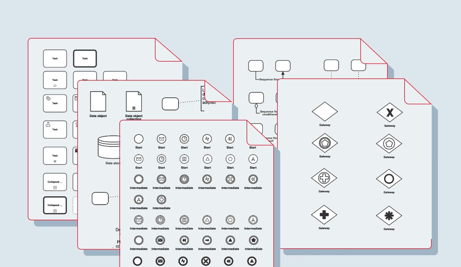
The BPMN 2.0 specification defines over 100 distinct visual symbols, but many diagramming tools make the decision to ship only a subset of the modeling notation. This decision is problematic, however, because it permanently locks your solution out of being able to import and render diagrams that contain elements outside that subset. A good modeler is able to render the full shape set of BPMN out-of-the-box, including:
That said, supporting all 100+ shapes does not mean surfacing every one of them to your users. A good diagramming product makes it straightforward for you – the developer – to restrict the visible palette to a curated subset of BPMN elements which are appropriate for your users' domain. The distinction between "supported by the engine" and "exposed in the palette" is an important one, and a good modeler is flexible enough to keep those two concerns separate.
However, placing shapes on a canvas is only the beginning. Enforcing the rules about how those shapes may connect and contain one another is where most custom implementations fall short.
BPMN defines a substantial set of semantic constraints that your modeler should enforce at interaction time, not just at validation time. For example:
Enforcing these rules interactively – preventing invalid connections, auto-enclosing elements when a pool is dropped, and giving users real-time feedback – requires deep integration between the shape model and the interaction layer. It is one of the areas that diagramming libraries like JointJS can handle for you, and one of the areas that takes the longest to implement correctly from scratch.
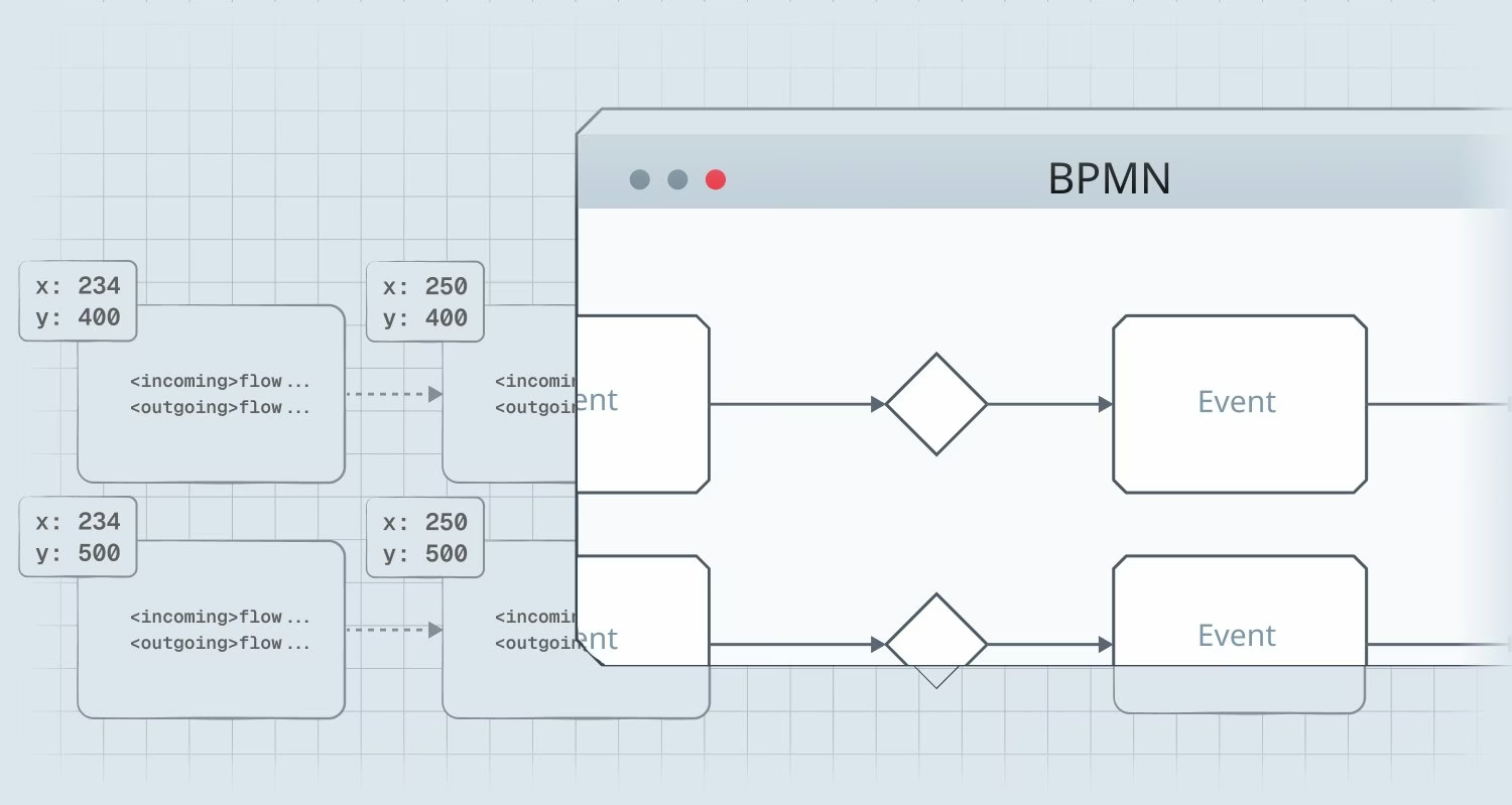
Implementing zooming and scrolling functionality is not trivial. The complexity hidden in this area can be separated into several sub-features which interact with each other in ways that can introduce subtle bugs (…ask us how we know). A production-grade modeler needs:
The overarching problem is that when zoom functionality is introduced, it suddenly becomes possible for client coordinates (i.e. the user's viewport into the graph) and graph coordinates to diverge – and every feature that touches element positioning (drag-and-drop, snaplines, property panels, link routing) must account for this transformation where previously it did not. Discovering this gotcha late in development is expensive.
A similarly deceptive feature is link routing. It may look simple at first glance, but in reality, link routing is one of the most complex subsystems in a diagramming library – and (like with canvas navigation functionality) its quality is immediately visible to your users. We consider it helpful to think of link routing in terms of the following seven functions:
In our experience, the effort to implement link routing from scratch is comparable to the effort to implement all of the core rendering foundation. That is why relying on a battle-tested library foundation here is almost always the right call.
The element palette – the sidebar from which users drag new shapes onto the canvas – is the primary way your users will interact with your BPMN modeler, so its capabilities must be well integrated into the rest of your modeler's functionality. A palette worth shipping includes:
Note that we consider snaplines and palette drag-and-drop to be coupled concerns. Even if you implement palette drag-and-drop correctly without snaplines, adding snaplines later is likely to force a rewrite of the drag layer. Plan for snaplines from day one.
Every user action that modifies the diagram should be reversible in intuitive chunks. In a BPMN modeler, that means undo/redo must understand compound operations, not just individual property changes. This is because deleting a single BPMN element may trigger a cascade of other deletions – especially when pool containment hierarchy or boundary event attachment rules are involved.
To understand what we mean, consider everything that must happen when a user deletes a deeply connected task. For example, a task that has one incoming sequence flow, one outgoing sequence flow, and an attached boundary event with its own outgoing flow requires five deletions in total. The correct undo behavior restores all five affected elements as a single atomic operation. An implementation that restores them only one-by-one (or one that loses an element entirely) would erode user trust immediately.
A solid undo/redo implementation requires a command history system that groups all related changes into distinct transactions. Diagramming libraries typically provide this infrastructure to you – however, you should verify whether your chosen library can handle BPMN-specific compound operations correctly, as we outlined above.
The property panel is where BPMN-specific complexity is concentrated. Remember that a task in BPMN is not just a labeled box – it carries a type (serviceTask, userTask, scriptTask), a name, documentation, and potentially dozens of engine-specific extension properties. A complete property panel implementation thus requires:
Getting property panels right is a significant design investment. JointJS addresses this with its Inspector component, which is fully integrated with its graph data model – changes in the panel propagate to the diagram and to the exported XML automatically.
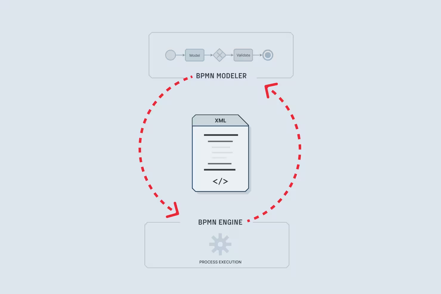
A BPMN modeler that cannot faithfully serialize its diagram state to standard BPMN 2.0 XML – and deserialize it back without loss – cannot ever be considered production-ready. But implementing import and export correctly is harder than it seems.
The checklist here has two parts. First, standard compliance – the exported XML must conform to the BPMN 2.0 schema, with both the semantic layer (<bpmn:process>) and the diagram interchange layer (<bpmndi:BPMNDiagram>) populated correctly. Schema ordering requirements (flow elements before artifacts within <process>) must be enforced explicitly, because engines like Camunda validate schema compliance strictly at deployment time.
The second, more subtle, consideration is round-trip safety for engine-specific extensions. Real-world BPMN files contain extension elements in proprietary namespaces (e.g. zeebe:, camunda:, flowable:) that your modeler might not understand natively. A naive XML import would silently discard those elements. A robust modeler must instead make sure to implement an explicit strategy for preserving unrecognized XML through the round trip, like the extract-mark-restore pipeline in our Camunda integration tutorial.
Round-trip safety is not a nice-to-have. If your modeler fails in this area, your users may lose configuration data silently – a class of bug that is difficult to detect and painful to debug.
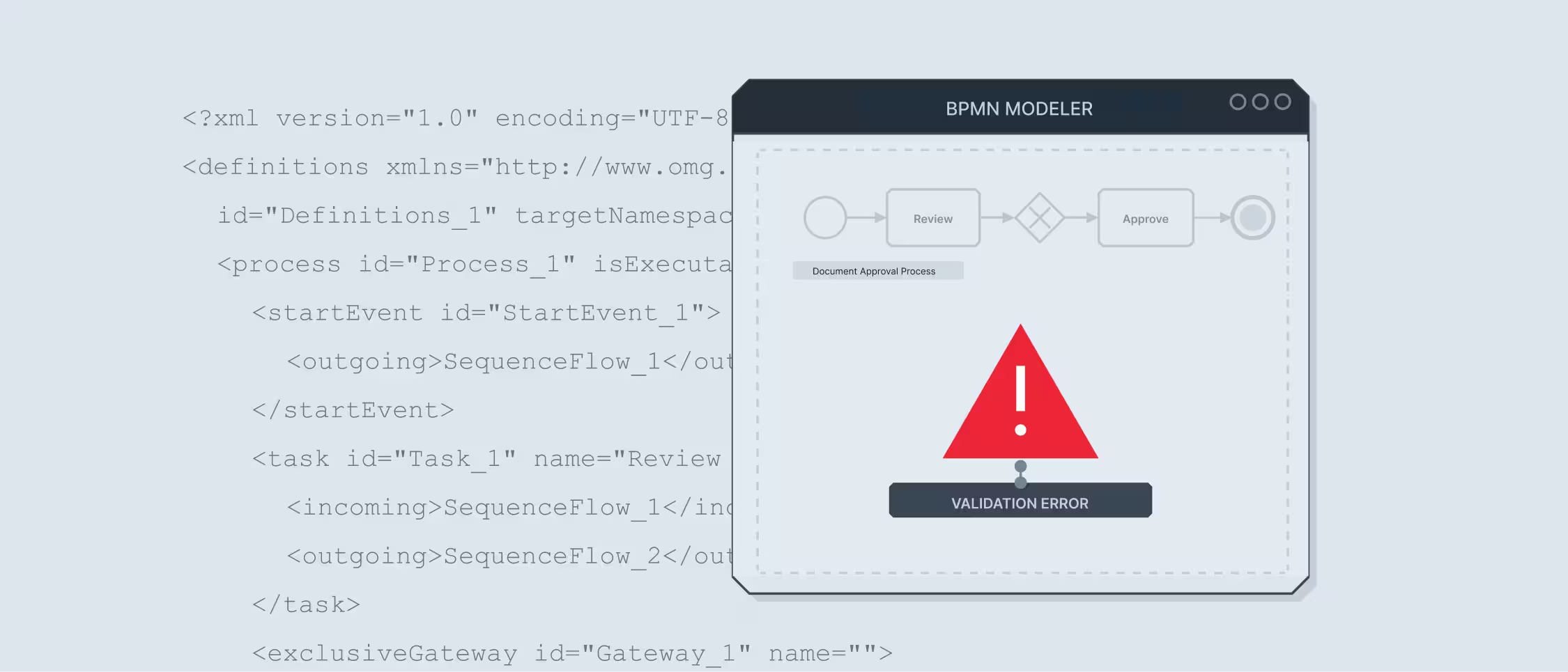
Your modeler should prevent users from trying to deploy invalid processes. Validation in a BPMN modeler has two distinct levels, and both of them matter.
The first is structural validation. This means enforcing BPMN's own rules – no disconnected sequence flows, no unreachable elements, required start and end events, correct event attachment. Many of these rules can be enforced interactively (see section 2), but a full validation pass before export is still valuable as a catch-all measure.
The second is engine-specific validation – i.e. checking that every element carries the extensions its target engine requires. For Camunda 8, this means verifying that every service task has a <zeebe:taskDefinition> with a type attribute, that isExecutable="true" is set on the process, and that HTTP connector tasks have all required I/O mapping inputs. These rules are engine-specific and cannot be derived from the BPMN spec alone – they must be implemented with explicit knowledge of the target engine's requirements.
A good modeler UI is able to present any validation errors understandably – directly on the offending element, ideally. This reduces the time between your user being "finished" with a process and actually having the process deployed and running in production.
Finally, a modeler that handles fifty-element diagrams smoothly but stutters at five hundred is not ready for enterprise use. Therefore, make sure to test rendering performance early, before the architecture is locked in.
The core risk is unoptimized SVG rendering. Even though SVG is the right choice for a diagramming tool (since it offers per-element event handling, CSS styling, and accessibility advantages that canvas-based approaches do not), naively rendering all elements as DOM nodes regardless of viewport visibility leads to performance degradation that tends to only surface with large real-world diagrams.
The solution is virtual rendering – i.e. dynamically removing elements from the DOM when they get scrolled out from the viewport, and re-adding them when they get scrolled back in. JointJS implements this out-of-the-box, while bpmn-js does not, which is a documented limitation when working with diagrams of several hundred elements.
A BPMN modeler UI is only as good as the interaction it enables to your users. In this article, we covered the ten feature areas that most prominently separate a production-grade tool from a prototype:
💡 Save this checklist for later — download the PDF version to share with your team, or use it as a reference when evaluating BPMN modeling tools.
Not every use case demands every one of these features at launch. But knowing which functionality is deceptively hard to add after the fact – i.e. the features on the above list – is what should let you scope the work correctly for your application's version 1.0, and beyond.
If you are evaluating diagramming libraries to serve as a foundation for your modeler, the JointJS BPMN Editor demo is a practical reference point. It covers the rendering, interaction, and palette layers out-of-the-box, leaving your team free to focus on engine integration and domain-specific customization – which is where your real product differentiation lives.
Happy diagramming!


.png)


.jpg)
