
When starting to work with BPMN 2.0 to develop workflow automation solutions, it is common to treat the BPMN modeler and the execution engine as a single tightly coupled stack. This is hardly surprising since most BPMN platforms ship their own modeling tools, and their documentation often presents modeling and execution as two sides of the same product.
However, the BPMN standard was explicitly designed to allow these two concerns to be separated. Understanding this distinction, and when it makes sense to leverage it, opens up far more architectural flexibility than developers initially expect.
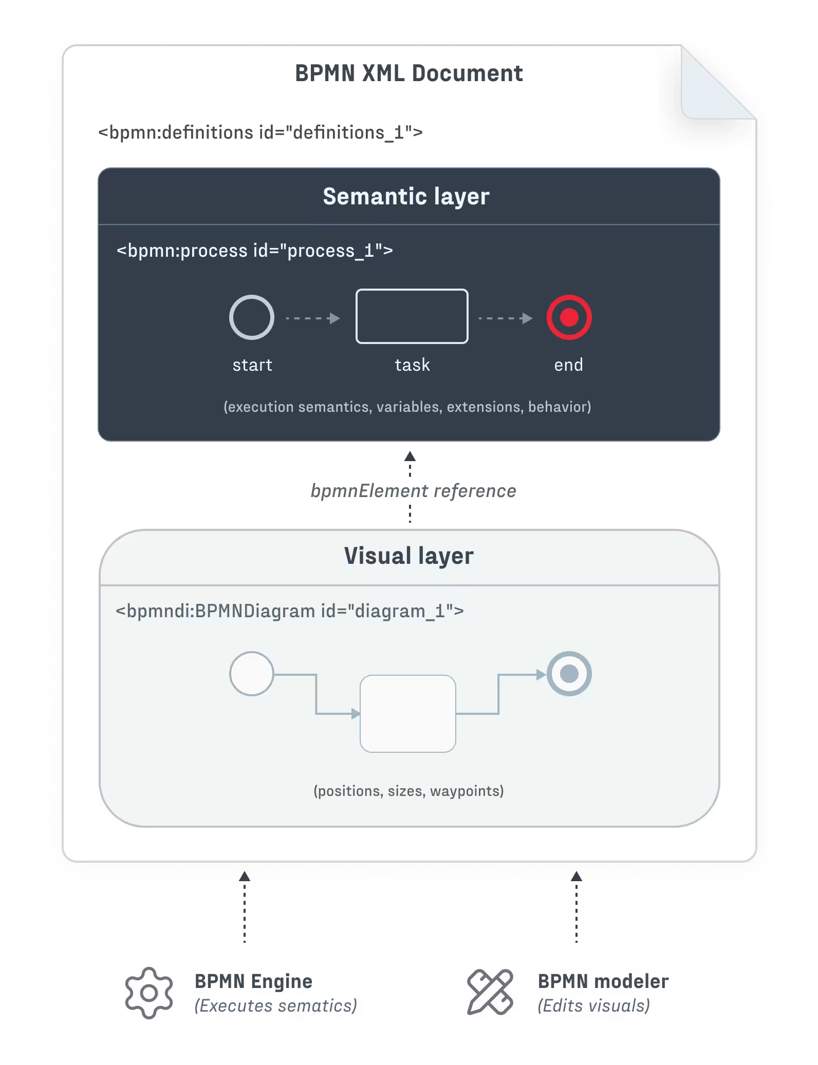
One of the key architectural outcomes of BPMN 2.0 is a clear separation of concerns between process definition and diagram presentation. Each BPMN 2.0 XML document describes a single business process in terms of two separate layers:
<bpmn:process> XML element).<bpmndi:BPMNDiagram> XML element).These two layers were explicitly designed to be decoupled. In principle, this means that any BPMN-compliant modeler can produce process definitions which are understandable by any BPMN-compliant execution engine. The BPMN modeler does not inherently need knowledge of the engine that will execute the process (and vice versa), and the BPMN 2.0 XML serves as the complete interface between the two layers.
In practice, execution engines introduce extensions, constraints, and engine-specific behavior, which complicate the picture. Nevertheless, the foundational separation remains valuable. Even though BPMN does not guarantee portability between different engines, its standardized structure enables architectural choices which would probably not exist otherwise – for example, to execute business processes on a Camunda engine while using a standalone BPMN modeling library (or even a fully custom-built modeler) as the user interface. (Similarly, an organization could choose to adopt an existing BPMN modeling tool while building a domain-specific execution engine tailored to its needs.)
In other words, the design of BPMN allows you to choose to spend development resources exactly where you need to, and rely on the work of others where you can afford to do so.
Let's dive in to understand how this separation works in practice, and let’s start from the beginning – the BPMN standard.
At its core, the OMG BPMN 2.0 specification defines a clear separation between process semantics and diagram presentation. In the semantic layer, the standard defines the building blocks of process logic and execution behavior – tasks, events, gateways, and the relationships between them. Meanwhile, the visual layer facilitates diagram interchange by storing graphical information like element positions, dimensions, and edge waypoints.
The linking mechanism between these two layers is a reference-based relationship. Each semantic element (for example, a <bpmn:serviceTask>) has an id attribute, and each visual element (for example, a <bpmndi:BPMNShape>) points to one semantic element by storing its ID in the bpmnElement attribute. The result may look like this:
<?xml version="1.0" encoding="UTF-8"?>
<bpmn:definitions xmlns:bpmn="http://www.omg.org/spec/BPMN/20100524/MODEL"
                  xmlns:bpmndi="http://www.omg.org/spec/BPMN/20100524/DI"
                  xmlns:dc="http://www.omg.org/spec/DD/20100524/DC"
                  xmlns:di="http://www.omg.org/spec/DD/20100524/DI"
                  id="definitions_1">

  <!-- SEMANTIC LAYER: Process Logic -->
  <bpmn:process id="process_1" isExecutable="true">
    <bpmn:startEvent id="start_1">
      <bpmn:outgoing>flow_1</bpmn:outgoing>
    </bpmn:startEvent>
    <bpmn:serviceTask id="task_1" name="Process Order">
      <bpmn:incoming>flow_1</bpmn:incoming>
      <bpmn:outgoing>flow_2</bpmn:outgoing>
    </bpmn:serviceTask>
    <bpmn:endEvent id="end_1">
      <bpmn:incoming>flow_2</bpmn:incoming>
    </bpmn:endEvent>
    <bpmn:sequenceFlow id="flow_1" sourceRef="start_1" targetRef="task_1" />
    <bpmn:sequenceFlow id="flow_2" sourceRef="task_1" targetRef="end_1" />
  </bpmn:process>

  <!-- VISUAL LAYER: Diagram Interchange -->
  <bpmndi:BPMNDiagram id="diagram_1">
    <bpmndi:BPMNPlane id="plane_1" bpmnElement="process_1">
      <bpmndi:BPMNShape id="start_1_di" bpmnElement="start_1">
        <dc:Bounds x="182" y="102" width="36" height="36" />
      </bpmndi:BPMNShape>
      <bpmndi:BPMNShape id="task_1_di" bpmnElement="task_1">
        <dc:Bounds x="270" y="80" width="100" height="80" />
      </bpmndi:BPMNShape>
      <bpmndi:BPMNShape id="end_1_di" bpmnElement="end_1">
        <dc:Bounds x="422" y="102" width="36" height="36" />
      </bpmndi:BPMNShape>
      <bpmndi:BPMNEdge id="flow_1_di" bpmnElement="flow_1">
        <di:waypoint x="218" y="120" />
        <di:waypoint x="270" y="120" />
      </bpmndi:BPMNEdge>
      <bpmndi:BPMNEdge id="flow_2_di" bpmnElement="flow_2">
        <di:waypoint x="370" y="120" />
        <di:waypoint x="422" y="120" />
      </bpmndi:BPMNEdge>
    </bpmndi:BPMNPlane>
  </bpmndi:BPMNDiagram>
</bpmn:definitions>This architecture has several important consequences:
These properties of BPMN explain why modelers and execution engines are not inherently coupled, even though many tools present them as a single integrated stack.
The architectural separation between BPMN modeling and execution becomes valuable when workflow tooling is part of a broader product strategy, and not just an internal concern. In such cases, off-the-shelf BPMN platforms often impose constraints and compromises that are difficult to accept. Common scenarios include:
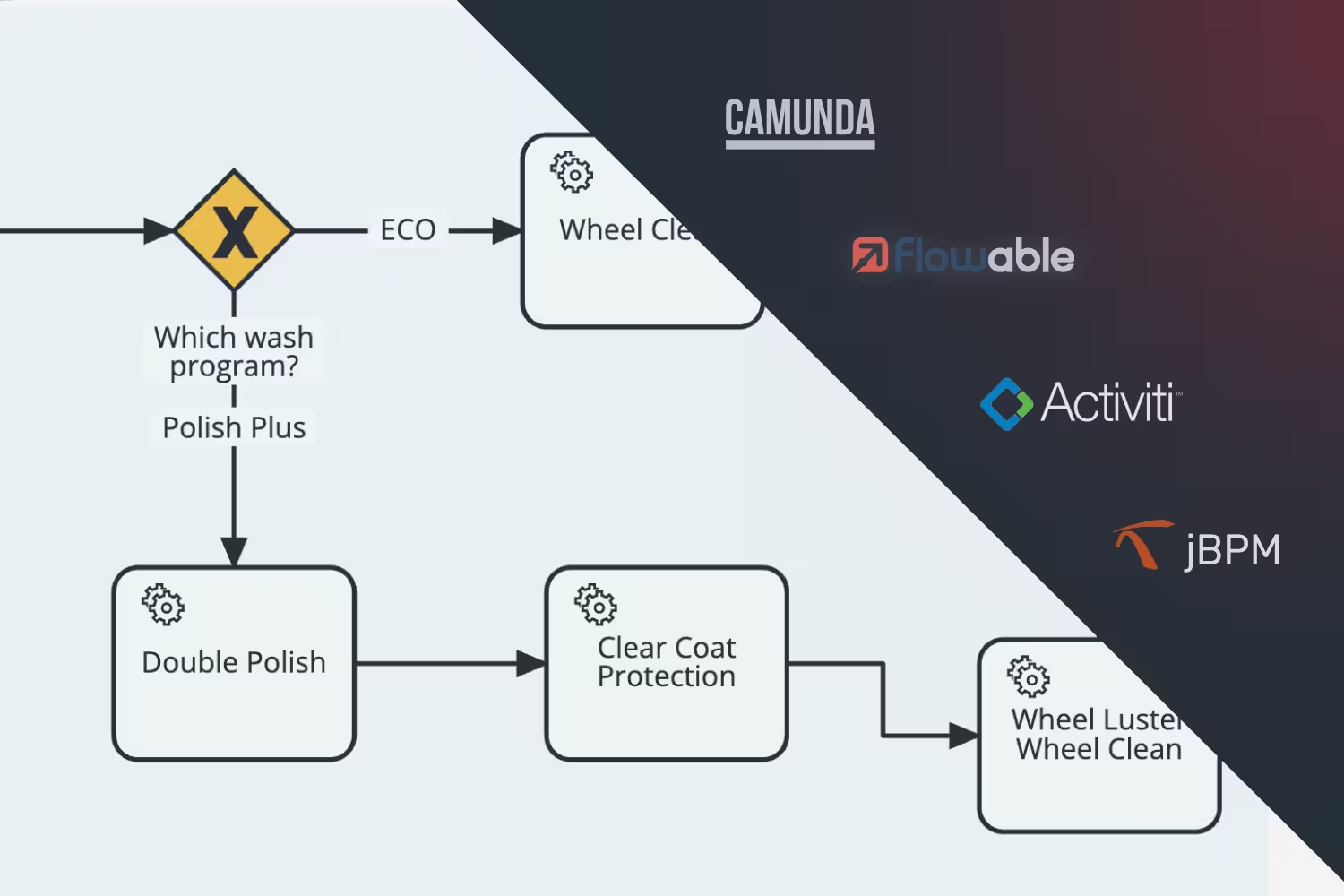
While BPMN 2.0 defines a clean separation between process semantics and diagram presentation, it was also made intentionally extensible. Many execution-relevant details are left unspecified in the standard and are instead defined by individual engine implementations. Each major BPMN execution engine fills these gaps using proprietary extension namespaces, execution semantics, and configuration models.
These extensions are the primary reason why BPMN files created for one engine most often require modification before they can be executed on another. They are also the reason why any custom BPMN modeling UI must be aware of the requirements of its target engine, and be able to accommodate them.
Let’s consider a common task – defining a BPMN service task that sends an email. Although the BPMN element itself is standardized, the execution details vary significantly across engines.
Camunda 8, which runs on the Zeebe engine, uses the zeebe: namespace with a job-worker architecture:
<bpmn:serviceTask id="sendEmail" name="Send Notification">
<bpmn:extensionElements>
<zeebe:taskDefinition type="send-email" retries="3"/>
<zeebe:ioMapping>
<zeebe:input source="= customerEmail" target="recipient"/>
<zeebe:input source="= "Order Confirmation"" target="subject"/>
</zeebe:ioMapping>
</bpmn:extensionElements>
</bpmn:serviceTask>Meanwhile, Camunda 7, which runs on the older Camunda engine, uses the camunda: namespace with Java class delegation:
<bpmn:serviceTask id="sendEmail" name="Send Notification"
    camunda:class="com.example.delegates.SendEmailDelegate"
    camunda:asyncBefore="true">
  <bpmn:extensionElements>
    <camunda:inputOutput>
      <camunda:inputParameter name="recipient">${customerEmail}</camunda:inputParameter>
      <camunda:inputParameter name="subject">Order Confirmation</camunda:inputParameter>
    </camunda:inputOutput>
  </bpmn:extensionElements>
</bpmn:serviceTask>
And Flowable introduces its own flowable: namespace and configuration model:
<bpmn:serviceTask id="sendEmail" name="Send Notification"
    flowable:class="com.example.delegates.SendEmailDelegate"
    flowable:async="true">
  <bpmn:extensionElements>
    <flowable:field name="recipient">
      <flowable:expression>${customerEmail}</flowable:expression>
    </flowable:field>
    <flowable:field name="subject">
      <flowable:string>Order Confirmation</flowable:string>
    </flowable:field>
  </bpmn:extensionElements>
</bpmn:serviceTask>
Beyond structural extensions, different engines also diverge in expression language support. For example, Camunda 8 uses FEEL (Friendly Enough Expression Language), defined as part of the OMG DMN specification where expressions start with the = character. On the other hand, Flowable uses the Unified Expression Language (UEL), with expressions written as ${...}:
<!-- Zeebe field input defined via a FEEL expression -->
<zeebe:ioMapping>
  <zeebe:input source="= customerEmail" target="recipient"/>
</zeebe:ioMapping>
<!-- Flowable field input defined via a UEL expression -->
<flowable:field name="recipient">
<flowable:expression>${customerEmail}</flowable:expression>
</flowable:field>The differences between engines extend further into areas such as process variable handling, variable scoping rules, input/output mappings, data propagation semantics, and error payload handling. You can see many of these differences in the above example. Any BPMN modeler intended for real execution must take these engine-specific behaviors into account.
As a result, one of the key requirements when building a custom BPMN modeler (or when selecting a diagramming library to build one) is the ability to adapt the modeling experience to the constraints and extensions of a specific execution engine.
Here’s how the two approaches to building a user-facing BPMN modeling application (monolithic vs. decoupled) may play out. Let’s assume that Camunda 8 is already used in the backend as the execution engine for internal workflows.
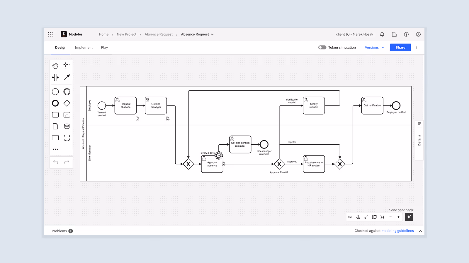
The decision may be taken to stick with Camunda’s environment and adopt Camunda Web Modeler as the modeling UI. This approach has some undeniable advantages: the integration itself is seamless (since the modeler natively understands the engine’s extensions), predefined Camunda connectors work out-of-the-box, and process deployment to the engine is handled automatically. This approach is probably the correct choice if you are building an internal-only automation for a small set of users, with no branding requirements, and with only a low amount of customization required. In these cases, using a vendor's modeling solution (such as Camunda Web Modeler) is the simplest way to deliver business process modeling functionality to your users.
However, as the required solution becomes bigger and needs to support more users and more customization, serious drawbacks to this decision start to emerge, as well. Camunda Web Modeler is a separate app that cannot be embedded into user-facing products cleanly, and it does not support applying custom branding to the UI. Furthermore, if you are building a commercial SaaS product, then Web Modeler's rigid tenant and user model may prove the most limiting, since it does not align with the multi-tenancy and fine-grained access control expected by most SaaS customers.
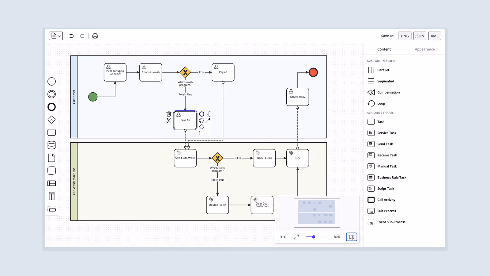
There is an alternative way. A separate diagramming library (such as JointJS) may be used to build a custom modeling frontend which communicates with the engine via API calls. JointJS’s customizability gives developers complete control over the user interface (including the layout of individual components such as toolbars, element palettes, and property editors and their look-and-feel), custom shapes whose styling conforms to the design of the rest of the application, and preconfigured shape setup that automatically includes all required engine extensions. For example, when a “Send Email” task is dragged into the diagram, the element may already be configured with the correct task definition type and input/output mappings, so that non-technical users never need to see raw BPMN 2.0 XML when working with the app (i.e. using BPMN exactly in the way how the creators of the standard intended).
Once you have a BPMN XMLDocument of your modeled process (e.g. from JointJS's toBPMN() function), it can be deployed to Camunda 8 via a REST API:
const bpmnXmlDoc = toBPMN(paper).xml; // JointJS example

// Deploy to Camunda 8
async function deployToCamunda8(bpmnXmlDoc) {
  const serializer = new XMLSerializer();
  const bpmnXmlString = serializer.serializeToString(bpmnXmlDoc);

  // NOTE: BPMN file extension needs to be `.bpmn`
  const bpmnFile = new File([bpmnXmlString], 'process.bpmn', {
    type: 'application/xml',
  });

  const formData = new FormData();
  formData.append('resources', bpmnFile);
  // ...and other properties, e.g. `'tenantId'`

  // NOTE: exact <host> endpoint and authentication mechanism differ
  // - depends on whether Camunda 8 is self-managed or SaaS
  const response = await fetch('<host>/v2/deployments', {
    method: 'POST',
    headers: { /* authorization */ },
    body: formData,
  });

  if (!response.ok) { /* error handling */}

  return response.json();
}
The same pattern works for Camunda 7, whose REST endpoint is <host>/engine-rest/deployment/create, except it also requires the formData['deployment-name'] to be provided, and the BPMN file is usually sent in as formData['data']. Flowable is also very similar, but its REST endpoint is <host>/flowable-rest/service/repository/deployments, and the BPMN file is usually sent in as formData['file'].
Clearly, this second scenario is more applicable to the sort of development which takes place in the real world – where well-directed user experience, consistent brand identity, and intuitive simplicity are the most desirable qualities of a user-facing application. However, the flexibility of a decoupled solution does come with some additional technical challenges and/or opportunities, depending on one's point of view:
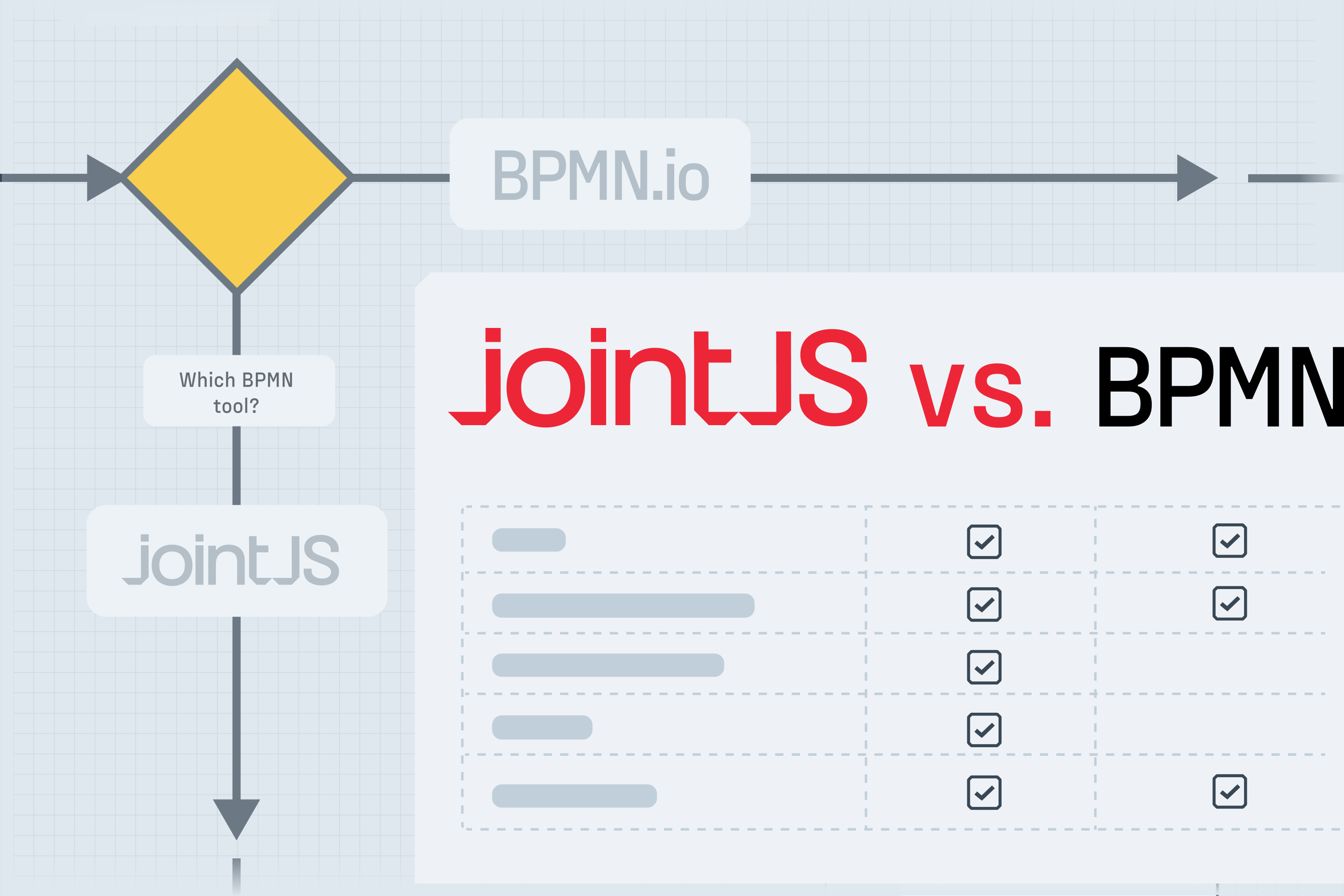
You may choose to develop a fully custom solution, but we believe that choosing a partner for the journey is a better idea. Let’s have a look at the main players on the market.
When building custom BPMN modeling interfaces in JavaScript, two libraries dominate the conversation: bpmn-js (maintained by Camunda), and JointJS (more specifically, the library’s commercial version JointJS+).
Although there are other diagramming libraries on the market, we will not be discussing them here because their BPMN offerings are lacking – bpmn-js and JointJS are the only major diagramming libraries on the market which support the full breadth of BPMN shapes and import/export of BPMN 2.0 XML files.
The two libraries are similar in several important aspects:
At the same time, the two libraries follow fundamentally different philosophies, which leads to distinct tradeoffs around BPMN validation, BPMN XML round-trip safety, and engine awareness. The table below summarizes how the different approaches translate into specific features and capabilities for each library:
These differences make bpmn-js and JointJS suitable for different use cases. The following sections examine each library in detail, exploring their respective strengths and weaknesses. Nevertheless, note that if neither library satisfies your needs, the option to implement your own modeler from scratch always remains on the table – although beware that the amount of development effort required to go this route is substantial.
bpmn-js is a BPMN-specific library built on top of diagram-js and maintained by Camunda, which powers the popular bpmn.io web tool. The library is open source and free to use, which is why it tends to be the go-to suggestion whenever someone inquires about the feasibility of building a custom BPMN modeling UI.
The library focuses on BPMN diagramming in general and Camunda execution engines specifically, which has its advantages and disadvantages. On one hand, bpmn-js will not help you much if you need anything other than BPMN modeling. On the other hand, as a BPMN-specific library, it enforces many BPMN validation rules by default and as such eases the modeling journey for your users. In addition, as a primarily Camunda supported project, bpmn-js is natively aligned with the rest of the Camunda ecosystem – it is round-trip safe for Camunda execution engines, and it assumes Camunda engine's semantics in many defaults.
However, its license imposes a significant constraint – the bpmn.io project watermark must remain fully visible in all rendered diagrams, and the source code for displaying this watermark cannot legally be modified or removed. For applications where license compliance and branding matters – i.e. commercial SaaS products – this requirement is often unacceptable.
Additionally, as a free library, bpmn-js offers only limited documentation for non-standard or advanced customization. Since no support subscriptions are available, this means that developers working with the library may have to rely on source code reading and community forums when they get stuck on a problem.
JointJS takes a fundamentally different approach from bpmn-js. The base library is truly free and open source, and provides the architecture for customizable interaction with diagram shapes, links, layouts, and visual styling. Its commercial extension, JointJS+, adds comprehensive BPMN 2.0 support and a wealth of customizable UI components – without a watermark requirement.
Being a general diagramming library, JointJS is explicitly execution engine agnostic. While this is unambiguously advantageous for support of non-Camunda engines (when compared to bpmn-js), it does come with technical tradeoffs. For example, JointJS makes it the developer's responsibility to validate the correctness of the modeled BPMN processes, to ensure round-trip safety of BPMN XML (via explicit handling of unknown XML namespaces, BPMN extension elements, and engine-specific metadata), and to conform to engine-specific requirements. At the same time, this means that JointJS offers the freedom to implement custom validation rules that exactly match a specific engine or domain in a way bpmn-js does not.
JointJS supports virtual rendering – the library dynamically renders only those SVG elements which are visible on the screen while removing invisible elements as the user pans and zooms. This addresses the performance limitations of SVG which affect bpmn-js when working with large diagrams (hundreds of elements). Unlike bpmn-js, JointJS also comes with touch support, which matters for tablet- and mobile-based use cases.
As a mature commercial library, JointJS focuses on providing return on investment to its customers by keeping a keen eye on the quality of its documentation and the amount of examples that can be used to kickstart the development of production applications. It pays off. In the words of Oleksandr Klimenko, Product Development Architect at BMC:

JointJS also offers commercial support plans, which prove valuable to developers who need to get verified answers to their customization questions with quick response times. As Bartek, Senior Software Engineer at ConSol, put it:

… bpmn-js:
… JointJS:
The separation of concerns introduced by the BPMN 2.0 standard enables BPMN modeling UIs and BPMN execution engines to be decoupled. In theory, the semantic layer consumed by execution engines is completely independent of the visual layer produced by modeling tools. Even though there are complications in practice – different engines rely on different execution semantics, extensions, and validation rules – BPMN 2.0 makes it possible to build modeling UIs in the frontend that operate independently of the execution engine used in the backend.
As a result, your choice of execution engine does not inherently constrain your choice of modeling interface. Camunda 8, Camunda 7, Flowable, and all other BPMN-compliant engines consume BPMN 2.0 XML files via API calls. The extensions that each engine requires can be generated (and preserved) by any modeling tool that offers sufficient customization capabilities.
Whether you are building a BPMN modeling UI to satisfy internal users, external customers, or specialized compliance requirements, JointJS provides the flexibility, performance, and stability needed to deliver production-grade applications. JointJS’s BPMN boilerplate application offers a practical starting point for your BPMN modeling implementation journey.
Happy diagramming! 👋


.png)